- Subscribe to RSS Feed
- Mark Topic as New
- Mark Topic as Read
- Float this Topic for Current User
- Bookmark
- Subscribe
- Printer Friendly Page
- Mark as New
- Bookmark
- Subscribe
- Subscribe to RSS Feed
- Permalink
- Report Inappropriate Content
Amplifier Manuals
- Mark as New
- Bookmark
- Subscribe
- Subscribe to RSS Feed
- Permalink
- Report Inappropriate Content
Re: test message
- Mark as New
- Bookmark
- Subscribe
- Subscribe to RSS Feed
- Permalink
- Report Inappropriate Content
Re: test message
- Mark as New
- Bookmark
- Subscribe
- Subscribe to RSS Feed
- Permalink
- Report Inappropriate Content
Re: test message
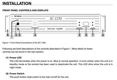
Oh, but that document needs some more information. Like features and a diagram
Product Features
SC-1250 Subwoofer Amplifier
• Amplifier: 3000 watts dynamic/1250 watts RMS high efficiency, Class D
• DSP-controlled
• 4 selectable presets for customized listening mode
• Automatic 7 band room equalizer (microphone included)
• Night-mode setting
• Mute control
• Adjustable (30 to 160 Hz) low-pass crossover (defeatable)
• Line-level (RCA) inputs and outputs
• Speaker-level inputs with 5 way binding post connections
• Signal sensing auto turn on/off (defeatable)
• Variable volume control
• Selectable phase control (0, 90, 180 or 270 degrees)
• Built-in adjustable digital low-pass crossover with 24 dB/octave slope
• Driver Displacement Control software to prevent over excursion and amp clipping
• Blue power indicator LED
• RS-232 Serial Interface
• 12 Volt trigger
• Universal remote input jack
• Ability to drive up to TWO subwoofers**
- Mark as New
- Bookmark
- Subscribe
- Subscribe to RSS Feed
- Permalink
- Report Inappropriate Content
Re: Amplifier Manuals
Don'f forget the Connections info:
Input Connections
Microphone Connections
These inputs are for two low-impedance balanced dynamic microphones. Connect cable shield to center screw marked "GND."
Auxiliary
The AUX inputs provide unbalanced RCA inputs for connection to
external signal-level equipment.
AUX Muting
For this function, a customer-supplied, normally-open contact closure
(switch) must be connected to the AUX2 and MUTE terminals.
When the contacts are closed, the AUX2 input will be muted.
Typically activated by a switch in a push-to-talk style microphone.
AUX 1, if selected, is not mutable by contact closure.
TEL
Connect the telephone line to the two outside terminals and the
shield, if used, to the center terminal. TEL input signal will trigger
automatic muting of AUX 1 and AUX 2. Input impedance is 600-ohm
and is transformer balanced. Input is for "Dry" audio signals only,
no DC voltage on the signal.
Output Connections
Speakers, General
The amplifier may be used with most conventional speaker
systems. Connect one speaker lead to the screw terminal that
corresponds to the impedance of the type of speakers used in
the system and the other lead to the COM terminal. If the line is
shielded, connect the shield to GND.
Connecting the GND to the COM terminal when using the
transformer-coupled outputs references the transformer output
to ground. Disconnecting the GND terminal from COM allows
the transformer output to float electrically. This is sometimes
useful under certain conditions where a ground connection is
undesirable. It is generally a good idea to short the GND to the
COM terminal regardless of output type (Trans or Direct).
Speakers, Low-Impedance
To connect a 4-ohm speaker, remove the the 4-ohm link and
connect the speaker between 4-ohm and GND.
Tape/Booster Connection
To record the amplifier program, connect a patch cord from the
TAPE/BOOSTER output jack to the input of a recording device.
Can also be connected to the input of a booster amplifier.
WMT1A Connection
This output jack is directly connected to the 25V speaker tap and
permits the connection of Bogen’s general-purpose matching transformer (WMT1A). The WMT1A steps the signal down by a 5:1 ratio,
giving you a 600-ohm balanced signal that can drive long cable runs.


